
One of the regional cliché phrases is that of a New Englander responding to a request for directions with, "You can't get there from here." Usually pronounced as "Ya cay-ent git they-uh from he-uh." Ok, it's funny to me.
One of the things that I find most challenging is mechanical interfaces. The sheer number of connectors and mechanisms just feels overwhelming. How to choose?
I started off thinking of the classic card-edge connectors and some sort of backplane. I gave serious consideration to the STD bus until my partitioning analysis showed that its 56-pin capacity wasn't nearly enough: the current partitioning requires 72 pins, including power and ground, and I want a bunch of free pins in case I need to repartition late in the process. I put the issue aside for a while.
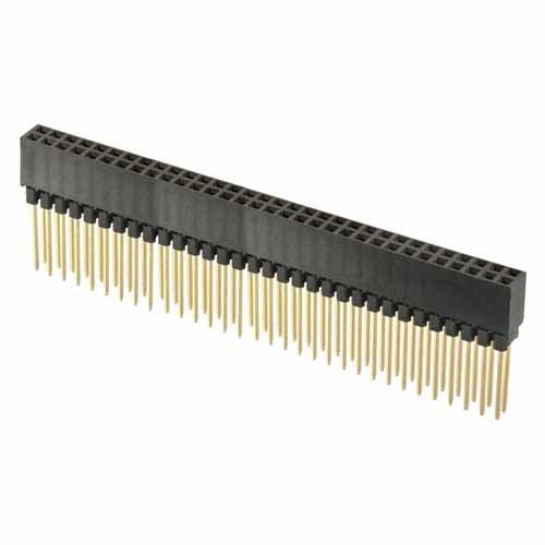 While cleaning up files from old projects I came across one that used a PC/104 board stack. PC/104 is an embedded computer form factor where various boards plug directly into each other without using a separate backplane. A PC/104 connector is mounted with the socket on the component side of the PCB. The pins of a "stackthrough" connector are long enough to go through the PCB and plug into the socket on the board behind it.
Here's a drawing from the PC/104 Consortium website showing how the boards stack:
 The original PC/104 spec implemented the old 8-bit ISA interface on a 64-pin connector. This was later extended to support the 16-bit ISA interface by adding a 40-pin connector, giving a total of 104 pins.
Although I have no intention of using the PC/104 card dimensions or connector pinouts, the connectors themselves are ideal for my purposes. Since all signals show up on all connectors the boards can be assembled in any order, giving easy access to whichever board is on top. Since I need more than 64 pins I'm putting a connector at each end of the board. My current drawings have a 64-pin connector on the right end and a 40-pin connector on the left, but I could easily put 64-pin connectors at each end for a total of 128 inter-board connections.
Here's a snapshot of the board layout as shown in the Eagle package editor, showing the connectors at the left and right ends of the board:

The dimensions at the left and bottom show the board dimensions: 6.6" x 4.25". This is somewhat larger than the maximum component area supported by my Eagle Standard license, depicted here by the dot-dash border line. Eagle's limit applies to component pins and pads, though, and not to signal traces; I can place components smack up against the legal area and still be able to route traces to them from any side. Thus I've made the board a little bit larger to be able to do that.
I started off thinking of the classic card-edge connectors and some sort of backplane. I gave serious consideration to the STD bus until my partitioning analysis showed that its 56-pin capacity wasn't nearly enough: the current partitioning requires 72 pins, including power and ground, and I want a bunch of free pins in case I need to repartition late in the process. I put the issue aside for a while.
While cleaning up files from old projects I came across one that used a PC/104 board stack. PC/104 is an embedded computer form factor where various boards plug directly into each other without using a separate backplane. A PC/104 connector is mounted with the socket on the component side of the PCB. The pins of a "stackthrough" connector are long enough to go through the PCB and plug into the socket on the board behind it.Here's a drawing from the PC/104 Consortium website showing how the boards stack:
Although I have no intention of using the PC/104 card dimensions or connector pinouts, the connectors themselves are ideal for my purposes. Since all signals show up on all connectors the boards can be assembled in any order, giving easy access to whichever board is on top. Since I need more than 64 pins I'm putting a connector at each end of the board. My current drawings have a 64-pin connector on the right end and a 40-pin connector on the left, but I could easily put 64-pin connectors at each end for a total of 128 inter-board connections.
Here's a snapshot of the board layout as shown in the Eagle package editor, showing the connectors at the left and right ends of the board:

The dimensions at the left and bottom show the board dimensions: 6.6" x 4.25". This is somewhat larger than the maximum component area supported by my Eagle Standard license, depicted here by the dot-dash border line. Eagle's limit applies to component pins and pads, though, and not to signal traces; I can place components smack up against the legal area and still be able to route traces to them from any side. Thus I've made the board a little bit larger to be able to do that.
No comments:
Post a Comment