Wednesday, February 28, 2024

Data bus charge redistribution

In my previous post I mentioned an anomaly I'd noticed in the data bus state during a period I believed it should be floating but stable.

Klaus Scheffler mentioned in his comments that he'd seen the same thing on his board. This got me wondering if I could use the simulator to help me understand this behavior. Sure enough, the sim also shows an indeterminate state on the data bus under similar conditions.

Monday, February 26, 2024

Internal data bus pre-charging

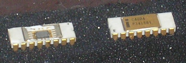
I "discovered" an interesting feature in the i4004 internal data bus management this weekend. Maybe the rest of you already discovered this, but it's new to me.

With the Scrachpad Register board working with my test program, I decided to mate it with the Instruction Pointer board I built in 2012. One of my goals was to see if the CLK1 and CLK2 circuits would ring, or if the rise and fall times are slow enough to avoid problems. To my great relief, I see no significant undershoot or overshoot on these circuits, and no ringing at all. Whew!

However, my logic analyzer showed some suspicious timing on the internal data bus. At first it wasn't clear to me what was happening, so I probed around a bit with my oscilloscope. As I was making notes of my observations I realized what was happening, and this also explained a bit of circuitry in the original chip I didn't previously understand.

Wednesday, February 21, 2024

The Scratchpad DRAM tests found a problem!

My DRAM test found an actual problem on the Scratchpad Register board!

Should I be excited that my test performed its function, or sad that there was a problem with the board?

The test is designed to work in concert with my logic analyzer. A PicoBlaze program implements the March C DRAM test, reading and writing the scratchpad registers repeatedly. If it detects that the data returned from a register isn't the expected value, it pulses an output. This pulse triggers the logic analyzer to log and display the signals it's been recording, which shows me what's been going into and out of the board for the last 25 i4004 instruction cycles. I'd tested this test setup in simulation, using the Verilog Scratchpad board emulation in place of the actual board, so I had some confidence that the test itself wasn't broken. But this was the first time I'd connected it to the real board.

What I saw was the error pulse indicating an error for essentially every attempt to read a scratchpad register. Looking more closely, I saw that the signalling going into the Scratchpad board looked correct, but the data being read was always 1111.
Monday, February 19, 2024

DRAM testing methodologies

Since I decided to do proper testing of my Scratchpad Register board, I thought I ought to invest some time in understanding the type of faults a DRAM array might have, and how to test for them. Given that the array on this board is only 8 rows of 8 bits I'm not really concerned with run-time, but I do want the tests to be thorough.

In my search for useful algorithms I came across this series of videos by Professor James CM Li of the National Taiwan University:

These are part of a much longer online course (94 videos) on VLSI Testing, but these three address testing RAM. The total run time for all three is only 1 hour 21 minutes. Professor Li speaks English with a pronounced accent, but his pace and careful enunciation make him easy to understand (unlike several videos by others I tried to watch).

I think I caught one small error in his explanation of the answer to one of his "quizes", but otherwise the content seems solid and is explained well.

Sunday, February 4, 2024

Scratchpad Register board signalling

One of the prerequisites for testing my Scratchpad Register Array board is to get a clear picture of the signalling necessary to make it function outside of the rest of the i4004 CPU's circuitry.

Years ago I split the i4004 CPU into functional chunks, each of which would become a separate PC board. In doing so I tried to keep related circuitry together to minimize the inter-board signalling. Thus the Scratchpad Register board includes many subcircuits:

  • 8-row x 8-bit DRAM array
  • 3-to-8 row decoder
  • 3-bit row refresh counter
  • 3-bit address latch
  • 3-bit 2:1 address multiplexer
  • 4-bit 2:1 data output multiplexer
  • 4-bit 1:2 data input demultiplexer
  • Miscellaneous state decode logic

The inclusion of these subcircuits means the interface to the board is somewhat more complicated than it would be with direct access to the DRAM address and data signals.

To read and write the Scratchpad DRAM array, I need to emulate the execution of one of the i4004's instructions. The only instruction which allows a single Scratchpad register to be written is "XCH", which exchanges the contents of the accumulator and the specified register.