Tuesday, May 26, 2020

The i4003 Shift Register

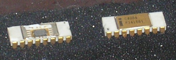
Intel 4003 shift register
The last of the original MCS-4 chips I need to emulate for the Busicom 141-PF re-creation is the i4003 shift register. I expected this to be simple: it's a 10-bit shift register with a clock input, a serial input, a serial output, 10 parallel outputs, and a parallel output enable input. How complex could this be?

In my mind I was picturing one Verilog always block for the shift register and a continuous assignment statement for the output enables. Four lines of code plus the module definition.

As it turns, the i4003 shift register is a more complicated chip than I expected.

Friday, May 22, 2020

i4001 data bus output timing

The next thing I wanted to try was to run the MCS-4 Digital Clock using the Instruction Pointer board I built in 2012.


In theory, all I should need to do is pull the Verilog IP module out of the clock project and replace it with the interface to the IP board. When I tried it, though, it didn't work.

Tuesday, May 19, 2020

XST conditional synthesis with Verilog generate

One of the purposes of creating my MCS-4 Digital Clock was to come up with something that would run on my hybrid debugging setup and give a clear indication of proper operation. This setup is the Digilent Spartan-3E Starter reference board connected to an expansion card that serves as a carrier for my i4004 CPU boards. This allows me to run the as-yet unimplemented parts of the i4004 CPU in the Spartan-3E FPGA.

Wednesday, May 13, 2020

An MCS-4 Digital Clock

Who needs yet another digital clock? Haven't we all done this before?


I did something like this in PIC-16 assembly language when I first connected my Microchip PICDEM-2 reference board to an LCD in 1999. (Anyone need a UV EPROM eraser?) I did it again in Verilog when I bought this Digilent Spartan-3E Starter board in 2009. But this digital clock is special: it's written in Intel MCS-4 Assembly language, and it's running on my emulation of an Intel 4004 CPU.

Monday, May 11, 2020

i4001 ROM emulation refactoring

This weekend I worked on the i4001 emulation, bringing the quick hack I did years ago closer to the operation of the actual chip. While doing this I've been wrestling with two conflicting objectives: making the emulation conform as closely as possible to the real i4001, while also using the hardware resources available in the Spartan-6 FPGA efficiently.


Tuesday, May 5, 2020

Another bug? I FIN you not

The FIN instruction is supposed to fetch the contents of the ROM location specified by the scratchpad R0R1 register pair, and store those contents into another scratchpad register pair. Obviously this didn't work properly or I wouldn't be writing about it.

A bug in my i4004 ALU implementation

Almost eight years ago I observed in Coding the ALU in Verilog that the i4004 arithmetic logic unit used positive logic for bits 0 and 2, and negative logic for bits 1 and 3. I thought this was odd but didn't ponder the matter for very long.

Last night I discovered a bug in my implementation of the ALU: if the accumulator contained 0x0 (4'b0000), executing the CMA (Complement Accumulator) instruction set the accumulator to 0x5 (4'b0101) rather than 0xF (4'b1111). Obviously this was wrong, and it bore a suspicious resemblance to the positive/negative pattern I'd noted before.

Sunday, May 3, 2020

Debugging the i4004 emulation

I had fantasies of just quickly hacking up the i4001 ROM and i4002 RAM emulations and loading the full Busicom 141-PF into my P170-DH board to see if it would run, but I've been an engineer for way too long to do that. Instead I've been plodding along, coding and testing each step of the way.

I'm not quite finished with the peripheral chips, but I felt good enough about their current state to finally start a simulation of a i4004 CPU connected to a i4001 ROM and a i4002 RAM in the Xilinx iSim simulator. For a test program I used the sample code that is loaded by default into Lagos Kintli's i4004 analyzer.