
Four hours after I started placing components I had everything picked, placed and soldered. I carried the board in its PanaVise holder from my soldering bench to my test bench and thought about what I wanted to test. I was pretty confident that everything was correct, but I decided to re-run the entire series of tests from the beginning. Everything looked good until I measured the +3V3 to ground and found an almost dead short. I thought, "What the hell?" and sat back for a moment. I couldn't see any solder bridges. I'd been so careful about the orientation of everything.
I remember checking the orientation of everything... except the FPGA itself. I remember checking the board to see where pin one should go, but I couldn't remember actually looking for the marking on the package itself. Looking at the chip on the board I was horrified to realize I'd mounted it rotated 90° clockwise. Somehow I'd managed to screw up the orientation of the single most critical, most sensitive, most expensive component. All I could do was hope that the ohmmeter hadn't put enough current through the FPGA to damage it. At least I hadn't applied power to the board!
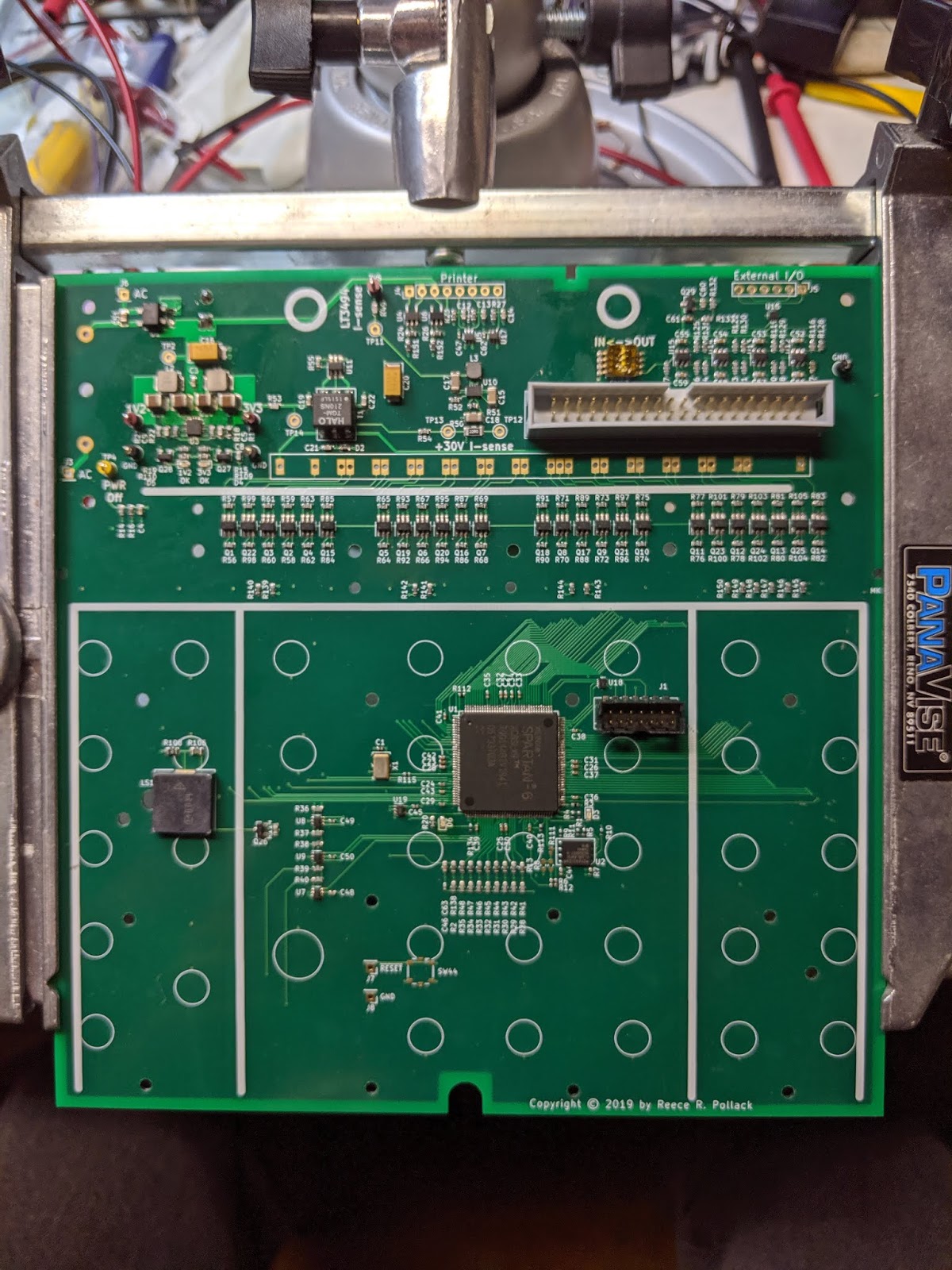
Once again I checked for shorts with my ohmmeter. This time there were no shorts. I connected my bench power supply and gingerly raised the voltage, making sure I was out of the line of fire should one of the chips decide to erupt like a volcano. There was a short blip in the current as the voltage regulators turned on, but otherwise the current draw stayed low.
Since the Flash ROM was blank I was expecting the FPGA configuration failure LED to come on, but it didn't. I found I'd installed it backward so I removed and reinstalled that correctly. Now when I applied power I got the expected response, which gave me hope that I hadn't damaged the FPGA. But the thing that gives me the most confidence is the burst of activity I saw when I probed the CCLK line at the Flash ROM with my oscilloscope.
To go any further I have to get the JTAG working, which means coding at least a basic Verilog test load. If the Xilinx JTAG tool recognizes the FPGA and loads a simple bitstream that'll be a huge step forward. I may get a chance to try that Saturday morning, but otherwise I'm pretty well committed for the next few days. Keep your fingers crossed!
No comments:
Post a Comment