Monday, June 29, 2020

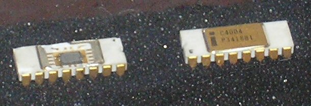
More bugs in the i4004 CPU emulation

I knew there was at least one lingering bug in the emulated i4004 CPU because I didn't see the contents of the OPA "register" output on the data bus during the X1 subcycle. But apparently the problems are bigger than that.

In my all-in test of the Busicom 141‑PF reconstruction, I noted several problems. To try and isolate the problem to one of the four emulated MCS-4 chips I decided I needed to test each of the emulated chips separately, starting with the i4001 ROM.

Wire, Tri, and Wor

Earlier today I cleaned up the VFD driver and the keypad remapping code so it was consistent with the rest of this project's code, and updated the top module for my P170-DH rebuild. Behavioral simulations ran fine, and synthesis and implementation gave only the expected warnings, so I decided to load it into the hardware and see how it ran.

At first I was pretty happy. The VFD displayed a single zero in the right-most digit, with the decimal point illuminated to just the right of the zero. The VFD driver reads the WR register, which is stored in RAM 0 register 1, via a dual-port interface to the RAM. Since an i4002 RAM clears itself to zeros while the reset input is asserted, this is what it should display. Unfortunately, that was the last part that worked as expected.

Saturday, June 27, 2020

First-Word Fall-Through FIFOs

Basic AXI Handshake protocol
Sometimes an engineer will see a technique on a website or in a document and think, "Wow! That's a good way to do that!" Such is what happened when I came across the AXI style handshake described in this Wikipedia article. I'd been looking for a good way for the M-32TL translator and printer modules to synchronize, and this seemed like a simple and well-tested mechanism.

This led me to consider the interface on the other side of the translator module, which is intended to talk to a FIFO. When I'd originally coded the translator I used a standard FIFO generated using ISE Coregen, figuring that was the best way to make sure the FIFO worked properly and was implemented efficiently. After discovering the AXI handshake I decided to re-implement it to use a First-Word Fall-Through FIFO because that allowed me to use the AXI handshake on both sides. Again I used Coregen.

If I wanted to run simulations using Icarus Verilog, though, I needed an alternative to a Coregen-constructed FIFO. Then I noticed that the Coregen FIFO used 27 slices for a 64 by 4-bit, common-clock FIFO. And I started looking at other FIFO implementations.

Friday, June 26, 2020

Translating EP102 codes to M-32TL codes

After recoding my EP102 printer emulation to send a stream of print drum sector numbers into the print buffer FIFO, I needed to develop some sort of translator to take those sector numbers and convert them to M-32TL print wheel sector numbers that the M-32TL printer driver could swallow.

This turned out to be harder than I expected.

An experiment with Icarus Verilog

Something I've given serious consideration is creating a simulated Busicom 141-PF using the Verilog Procedural Interface (VPI, aka PLI) to interface the simulated system with the outside world.

While many Verilog simulators support VPI, the Xilinx iSim simulator is not one of them. However, Icarus Verilog does, and as engineers do I started gathering data and doing experiments.

Monday, June 22, 2020

Timing diagram applications

I'm old-school enough that I draw most of my timing diagrams with graph paper, a pencil and a big eraser. I knew what I wanted the timing to look like for the module that translates EP102 printer codes to M-32TL printer codes, but this time I thought it might be nice to find an application to draw them.

In general I favor open-source apps, but I'm willing to consider something closed-source if the license terms are good. Here are the applications I found worthy of note.

Monday, June 15, 2020

Reworking the EP102 emulation

A few months ago I designed, coded, and started testing a Verilog module to emulate the EP102 printer found in the Busicom 141-PF calculator. I wrote a bit about it in the post EP-102 to M-32TL Glue logic

The EP102 is a drum printer capable of printing one of 13 characters in each of 17 columns.  When a row of characters is properly aligned for printing, the printer sends a "sector" signal to the computer. To allow the printer to identify which row is aligned for printing, a second "index" signal is sent when the first row is aligned. To print a given character, the computer waits until it sees the sector signal indicating that character is aligned for printing, then sends a signal to the printer that causes a mechanical hammer to press the paper against the drum. It thus takes one full rotation of the drum to print all the columns of that line.

My first task was to code a module that generates the print drum index and sector signals for the calculator, while tracking the active sector number. Since the sector number ranges from 0 to 12, it's represented by a 4-bit value.

Saturday, June 13, 2020

First trial of the Busicom calculator software

I've been slowly assembling a Verilog top module that will instantiate an emulation of the Busicom 141-PF calculator in the Spartan-6 LX9 FPGA in my rebuild Canon P170-DH calculator. With the emulation of all four required MCS-4 chips appearing to work properly, it seemed time to test it out.

The MCS-4 chips required for this are:
  • Five i4001 256 x 8-bit ROM with a 4-bit I/O port
  • Two i4002 20 x 4-bit RAM with a 4-bit Output port
  • Three i4003 10-bit serial-in, parallel-out Shift Register
  • One i4004 Central Processing Unit
To this I've added a clock driver that generates the two-phase clocks required by the MCS-4 chips.