Recently I've been shown that I'm not the only hobbyist with a touch of insanity.
I've already mentioned the folk behind 4004.com who have resurrected the 45-year-old Intel design for our education.
There's Robert C. Baruch, the self-named Half-Baked Maker, who is entertaining himself by reverse-engineering some old integrated circuits by stripping them layer by layer to develop a schematic diagram of their workings. This requires the use of nasty chemicals like hydrofluoric acid -- and people think I'm nuts for using tin/lead solder!
Personally, I think the person who most deserves the crazy inventor award is Sam Zeloof. He's creating working MOSFET transistors in his home laboratory. He recently acquired his own scanning electron microscope; can an unlicensed nuclear accelerator be far off?
My hat's off to you folk. You make me feel totally sane.

Experiments with the world's first microprocessor
and other electronic explorations
Monday, May 22, 2017
Monday, May 15, 2017
Packing worms into a can
Back a few years I threw the Verilog source code for the 4004 CPU at the Lattice toolchain and observed that it occupied "40% of the logic
cells and one of the 16 block RAMs" of an iCE40-HX1K FPGA. From this I felt that using an iCE40-HX4K part, which is 2.75 times the size, would be plenty to implement the entire Busicom 141-PF calculator system. Of course it'd be even nicer if I could use the HX8K part, 6 times the size of the HX1K, but it's only available in a BGA.
While trying to get the comma positioning working in the VFD driver code I took a look at the resource utilizations for two potential implementations. What shocked me was not the difference, but the total size: 492 of the 1280 lookup tables (LUTs). That's 38%!
Once I caught my breath I asked myself how this compared with the Xilinx parts I've worked with. So I built the same Verilog code using Xilinx ISE 14.7, specifying a Spartan 6 chip; it used 331 LUTs. However, the Spartan 6 has 6-input LUTs, versus the 4-input LUTs of the iCE40. Trying to find a more apples-to-apples comparison I built it yet again, this time specifying the Spartan 3E chip which also has 4-input LUTs. The Spartan 3E used 320 LUTs. Advantage Xilinx, whether by better architecture, better synthesis, or both.
But what was using all these LUTs? I thought over my code and really couldn't see any real hogs. Most of the selectors in the case statements are 4-bit quantities, which should require only one LUT per output bit to implement. Looking at the Xilinx ISE Map report I noticed a section for "Utilization by Hierarchy." Excellent! I enabled the detailed Map report and reran the mapper. To my great surprise it is the Digilent Adept I/O Expansion interface that is taking up the majority of the LUTs: 205 of 331 in the LX9, and 157 of 320 in the S3E. (I don't know how to get the same statistics out of the Lattice version of Synplify Pro).
While it's certainly a relief to find my VFD driver isn't the hog I thought it was, it does point out the risk of underestimating resource utilization. The Adept interface doesn't look very complicated -- it's only about 100 lines of Verilog -- but it takes a lot of resources. For comparison, the entire 4004 CPU and one 4001 ROM, which I think of as complex, requires only 400 S3E LUTs.
So back to the choice of chips for the calculator. I found I was able to do more with ISE in a shorter time, though whether that's better integration or just greater familiarity I'm not sure. The Xilinx tools and chips seem be more efficient in their use of resources than the Lattice. Finally, I can get the Spartan 6 LX9 in a TQFP-144 package, while the iCE40-HX8K is only available in a 0.8mm-pitch BGA. Yes, mounting a BGA scares me, but more importantly it would be infeasible with this design unless I made the board with blind vias and that would really jack up the cost.
I think that settles the matter. The Lattice iCE40 series is quite reasonable to work with, if you're looking for something small, power efficient, or are willing to stick with commercial boards. The toolchain is quite acceptable, even if you do have to obtain a new (free) license every year. But for my specific needs, I think the Spartan 6 LX9 is the best fit.
Why not Altera? They make fine chips. The answer, simply put, is that I don't know Altera, I don't have any equipment to program them, and I just don't have time or interest in adding yet another variable. They do see to have quite a selection of chips in hobbyist-friendly (i.e. non-BGA) packages, though. Some other project, perhaps.
Saturday, May 13, 2017
Not too shabby
Here's the Vacuum Fluorescent Display salvaged from the Canon P170-DH calculator driven by a Lattice iCE40-HX1K FPGA through my driver test board.


Tuesday, May 9, 2017
More data, but not more understanding
I continued poking around my VFD driver test board, looking for an explanation for why I need such strong pull-down resistors on the VFD grids. I know more than I did, but I still don't understand why.
Saturday, May 6, 2017
Who ya gonna call?
 |
| Grid Driver Configuration |
The Toshiba RN4604 I used in the anode and grid drivers contain two pre-biased bipolar transistors, one PNP and one NPN; the bias resistors are all nominally 47K ohms. Driving the CTRL input to +3.3V turns on Q1B, which drives Q1A into saturation and pulls the grid to +30V. With the CTRL input at ground Q1B and Q1A are off, and R2 pulls the VFD grid to ground. The ends of the filament swing ±2V around a point +6.8V above ground, so an inactive grid should be at least -4.8V with respect to the nearest filament segment.
I connected my oscilloscope to the VFD grid leads for the active and ghosting digits. When the active digit's grid went to +30V with respect to ground I saw the ghosting digit's grid rise to about +10V. That's about +3V wrt to the average cathode voltage, which attracts enough electrons to cause the active anode in that digit to fluoresce too. Although this is not a truly stable state and tended to dissipate over time, it appeared the pull-down resistor R2 wasn't doing its job.
Just to be sure I looked for any indication that the ghosting digit's grid driver was turning on spuriously, but I couldn't find any. The circuit is sensitive enough to turn on momentarily if you touch an undriven CTRL input, but wiring CTRL to ground didn't change the behavior. Scoping the input to the PNP transistor showed nary a wiggle even as the grid lead voltage rose.
I expected some leakage current on an inactive grid, but the datasheets I saw for ICs that had built-in pull-downs used 125K ohm resistors so I wasn't expecting much current on an inactive grid. I tried placing a second 100K ohm resistor atop the existing 100K pull-down resistor, giving an effective 50K ohm pull-down, and although that reduced the brightness of the ghost segment it didn't eliminate it. Given 10V across 100K ohms, the leakage current on the ghosting digit's grid must be about 100 uA. Hanging a through-hole 10K resistor to ground on the lead killed the ghost. That's probably excessively low, but I haven't been able to find any information on this VFD that would give an expected inactive grid current.
My best guess at this point is that there is some capacitive coupling between the grids within the tube, and it causes the adjacent grid to rise. The condition isn't stable because the charge eventually bleeds off through the pull-down resistor. But I don't really understand the mechanism at work here.
I don't have a lot of 0603 SMD resistors laying around so I decided to replace the 100K pull-downs on the grids with 10K resistors. This will cost me an extra 3mA on the active grid, but there's only one grid active at any time. Active anodes draw less than 600uA each, while there are always 2 to 9 anodes lit per active digit, so I decided to leave their pull-downs as 100K resistors.
Next I'll work on getting the FPGA to drive this thing.
Friday, May 5, 2017
Some Assembly Required
After spending an exhausting day listening to multiple presenters talking non-stop about the project at work, I was ready to do something completely different: assemble my VFD driver test board!
Here's a bare board sitting on the connectors to the Lattice iCEblink40-HX1K demo board I'm using as a driver test driver.

Here's a bare board sitting on the connectors to the Lattice iCEblink40-HX1K demo board I'm using as a driver test driver.

Thursday, May 4, 2017
Well THAT's not quite right!
The USPS delivered my PCBs from Osh Park today. They look fantastic! Except for one thing...


Tuesday, May 2, 2017
Interfacing a VFD with the Busicom emulation
Hey! Something related to the Intel 4004 for a change!
The Busicom 141-PF calculator didn't have an electronic display; its only output mechanisms were the printer and three lamps that indicated an overflow condition, a negative result, and a value stored in memory. Here's a photo of the keyboard of the 141-PF; you can see the indicator lamps along the top edge to the left of the power switch:
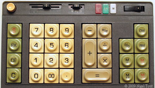
The Canon P170-DH calculator I selected as my base for this reconstruction has a Vacuum Fluorescent Display tube that can display 12 numeric digits plus "E", "M", and a minus sign in place of a 13th digit. Aside from not being able to display all 14 digits the 141-PF supported, this is a pretty close match. But how to make use of the display?
The Busicom 141-PF calculator didn't have an electronic display; its only output mechanisms were the printer and three lamps that indicated an overflow condition, a negative result, and a value stored in memory. Here's a photo of the keyboard of the 141-PF; you can see the indicator lamps along the top edge to the left of the power switch:
The Canon P170-DH calculator I selected as my base for this reconstruction has a Vacuum Fluorescent Display tube that can display 12 numeric digits plus "E", "M", and a minus sign in place of a 13th digit. Aside from not being able to display all 14 digits the 141-PF supported, this is a pretty close match. But how to make use of the display?
Some good news re Lattice
After bad-mouthing Lattice for dropping support for the USB programming interface to their iCEblink40 demo card, I got down to the business of coding my VFD Driver test board test driver.
For those who are insistent about using open-source code to the exclusion of all commercial products, there is an open-source toolchain for the iCE40 series of FPGA: Project IceStorm. That's really cool. If I was looking for an interesting hobby project this might be one, but I already have way too many irons in the fire as it is. Thus I'm using the Lattice-provided IceCube2 development environment.
IceCube2 is a fairly simple wrapper around your choice of two synthesis tools: the Lattice Synthesis Engine (LSE) and Synopsys Synplify Pro. LSE is part of the basic (free) license, while it appears that Synplify requires an extra-cost license. A "performance limited" version of Aldec Active-HDL is provided for simulation and debugging. Active-HDL is a major player in the Verilog/VHDL simulation market, and even the cripple-ware version appears to be on par with Xilinx Isim.
Normally I'd be saying "But Active-HDL won't run under Linux!" at this point, but I found a listing for it in the WineHQ database that gives it a Platinum rating. For non-geeks that means it appears to run very well under the Windows emulation environment in Linux.
I haven't tried to synthesize anything yet, but I may reconsider whether I want to put a Spartan-6 LX4 or an iCE40-HX4K in my calculator rebuild.
Subscribe to:
Posts (Atom)