
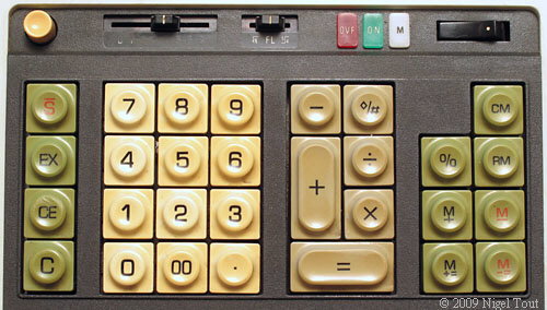
The Busicom 141-PF calculator didn't have an electronic display; its only output mechanisms were the printer and three lamps that indicated an overflow condition, a negative result, and a value stored in memory. Here's a photo of the keyboard of the 141-PF; you can see the indicator lamps along the top edge to the left of the power switch:
The Canon P170-DH calculator I selected as my base for this reconstruction has a Vacuum Fluorescent Display tube that can display 12 numeric digits plus "E", "M", and a minus sign in place of a 13th digit. Aside from not being able to display all 14 digits the 141-PF supported, this is a pretty close match. But how to make use of the display?
One option would be to hook it into the printer emulation so it displayed whatever was printed (or would have been printed) last. But that doesn't help when you're entering a new number. Remember that my replacement keyboard doesn't make a satisfying "click" when a key is depressed and the tactile feedback is a bit mushy. While I can (and will) generate a key click sound, I'd still rather see what's going on as I enter values. But how can I do that?
If the calculator was implemented in a single integrated circuit I wouldn't have many options. With a real 4004 system I could implement logic to snoop the bus and extract the data I need as it passes by. However, since most of the logic other than the CPU will be implemented in an FPGA, I can peek into the internal circuits and use the contents stored there.
An Intel 4002 RAM chip contains four 20 x 4-bit "registers", each of which is arranged as 16 "main memory characters" plus 4 "status characters". According to the excellent research conducted by Barry Silverman, Brian Silverman, Tim McNerney, and Lajos Kintli, the 141-PF software uses each of the 4002's registers to represent a 14 to 16 digit value, with each of the main memory characters containing one binary-coded decimal (BCD) digit and two of the status characters indicating the location of the decimal point and the sign of the value.
One of these registers is called the "working register" or WR. As the user enters a value on the keyboard, the software stores the value in WR one digit at a time. After a calculation the results are also stored in WR, again as a set of BCD digits. A status character in another register indicates the overflow condition.
This is ideal for my purposes! All I need to do is connect the WR register in an emulated 4002 to my VFD driver logic, which will display each BCD character on the VFD's 7-segment display. A multiplexer will switch the BCD characters from the WR register to the 7-segment decoder that will drive the VFD's anodes in synchronization with 13 grid drivers. The most complex bit of logic is that required to blank the leading zero digits.
Last weekend I coded most of the VFD Driver logic, and it seems to work pretty well in simulation. I haven't tried synthesizing it yet, nor have I looked up how to associate physical pins with internal signals. Eventually I want to code an interface to the Adept I/O expansion interface as means to control the test display from a computer. I'll see how far I get with it this weekend.
Speaking of the weekend, I just got notice that Osh Park received my boards from their fab and has shipped them to me. USPS says they should arrive Thursday, so I should be able to assemble the board Thursday or Friday evening. With any luck I should be testing the VFD driven by an FPGA next week. I'll post pictures when the boards arrive and during assembly.
No comments:
Post a Comment