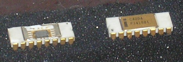
I took a look at the Instruction Decoder board this evening and discovered there were a handful of parts that not only hadn't been routed at all yet, they weren't even in a near-final placement. I really thought I'd gotten farther on this than I had.
It wouldn't show up on a screen shot so I'm not going to bother, but I juggled most of them into a reasonable layout and routed within the groups. I also took a look at what's left unconnected and, like the ALU board, switched from a 4-layer to a 6-layer stackup using the same layer assignments as the ALU.
Ratsnest now reports 16 VDD, 32 GND, and 85 other airwires. That's after I'd already routed a bunch of unconnected GND pads. Again, I'm a bit surprised these numbers, especially the number of GND airwires.
There's still some possibility that as I get close to the final routing I'll decide to go back to a 4-layer board. Since all the components except the connectors are surface-mount, I've routed as much as practical on the top layer to minimize the number of vias (and thus minimize the board area they occupy). Looking at only the bottom and inner layer there really isn't that much there. If it's practical to route the remainder using only these two, and if the power distribution will also fit, I might dispense with the extra two layers. Or maybe not.
Friday, February 26, 2016
Wednesday, February 24, 2016
Progress on the ALU board
With six copper layers to play with, routing the ALU board has gone from challenging (if not nightmarish) to relatively easy. When routing vertical traces I no longer have to consider how I'm going to get VDD to the various pads, and routing nets to the connectors is mostly a matter of keeping routing lanes free of vias to avoid having to weave around them.
Sunday, February 21, 2016
What's a couple layers among friends?
Ever notice that some projects seem most interesting when there's something else you're avoiding doing? Yeah, me too.
November 2016 will mark the 45th anniversary of the release of the Intel 4004. This is enough of a significant anniversary to make me feel a bit of a kick in the ass to complete the remaining four boards of the CPU this year.
November 2016 will mark the 45th anniversary of the release of the Intel 4004. This is enough of a significant anniversary to make me feel a bit of a kick in the ass to complete the remaining four boards of the CPU this year.
Monday, February 1, 2016
FDV301 turn-off characteristics
At first I thought it might be illuminating to add a resistor between the source of Q5 and Vss so I could see how much current was making it from Vdd though both Q4 and Q5 to Vss. I've been playing with the results for over a week now and just couldn't come up with a consistent explanation for my results.
I take that back. I've determined that there's so much noise between Vdd and Vss alone on the solderless breadboard that attempts to measure small signals accurately is extremely difficult. This despite a generous helping of bypass capacitors ranging from 0.1uF ceramics and 10uF tantalums to 200uF electrolytics. What seems to work best is using the oscilloscope in difference mode to measure the voltage across a single resistor. This seems to null out most of the Vdd fluctuations.
Eventually I moved R4 so it sat between Q4 and Q5 and measured the voltage across it. What I see is less than 2mA (200mV across 100 ohms) through that resistor during the low-to-high output transitions, and essentially nothing during the high-to-low transitions, regardless of which FET I use for Q4. That kinda kills shoot-through current a culprit.
To try to figure out where the current is going I modified the test circuit to put R4 in series with the gate of Q4. To minimize differences between my test circuit and the actual push-pull driver I reconnected the drain of Q4 to Vdd, and the source of Q5 to Vss.
Subscribe to:
Posts (Atom)
