
On the other hand, it might be nice to have the display to show what you're entering as you enter it. In a previous post here I gave thought to replacing the 12-digit VFD with a 2-line, 20-character VFD module from Noritake-Itron, which would let me display a lot of status information. However, though the height and width of the active display areas are compatible, the VFD module is much thicker than the tube of the built-in display. It's also heavier than I expected, so it'd need some structural support to keep it in place. Now I'm thinking it's more trouble than it's worth.
Another option would be to keep the existing 12-digit VFD and drive it from the same Spartan-6 FPGA that will emulate all the logic other than the CPU. This would require characterizing the existing vacuum fluorescent display tube before I remove it from the Canon calculator's electronics board. It carries a Samsung SSVD part number of INB-13SM36T but my attempts to come up with any sort of datasheet came up empty.
A VFD contains three types of elements: a heated filament that serves as a cathode; a set of grids, one per digit; and a set of phosphor-coated anodes, one per display segment. A non-multiplexed display of 12 7-segment digits would require 84 anode leads and 84 high-voltage drivers. Thus most displays are multiplexed.
The VFD from this calculator has 28 leads, so it's clearly using multiplexing. Two leads are connected to the filament and are labeled VF1 and VF2 on the calculator PCB. Let's start there.
If the filament is driven with a DC voltage there will be a voltage gradient across its length. This means the end of the display with the more positive filament voltage will have less of a differential to the anodes, and thus will be dimmer than the negative end of the filament. Don't believe me? Here's an image by M0AYF (that's a ham callsign) on QSL.net showing this effect:

While it's possible to construct a VFD with this in mind, the normal way to handle this is to drive the filament with an AC source. Here's a 'scope trace of the two ends of this display's filament:

With the vertical scale of 5V and the zero level at the top of rule of the display, we see the cathode is held at an average voltage of -18 VDC with a 5V square-wave AC signal superimposed that reverses polarity at about 133 KHz. I attempted to measure the filament resistance, but my ohmmeter says 0.6 ohms which is improbably low. Either I'm getting a sneak path through the unpowered electronics or the filament resistance rises as it heats (which is a known behavior of tungsten lamp filaments). I'll test it hot out-of-circuit after I separate it from the calculator board.
A VFD is basically a bunch of triodes in one package, with the gate and anode voltages manipulated to control which anodes gets hit with electrons. To make sure a given digit is kept dark, the grid for that digit must be driven negative with respect to the filament. Likewise, to keep a given segment of a selected digit dark the anode for that segment must be driven negative with respect to the cathode. By carefully probing around the various VFD leads I was able to identify two adjacent grids. Here's what I see, referenced to logic ground:

This shows this calculator drives the grid to +5V (the logic supply voltage) to enable a digit, and to -25V to disable it. With respect to the cathode (filament), the grid is driven to +23V to enable and -7V to disable a digit.
This display has 13 grids; one for each of the 12 digits plus one for a set of indicators. The indicator group lives at the left end of the digits and contains a minus sign (allowing display of a 12-digit negative number), an "E" (error), and an "M" (memory?). Each digit has 9 anodes; the standard 7-segment numeric, a decimal point, and what looks like an apostrophe but used like a comma to separate thousands.
I then probed the VFD leads again to identify which lead corresponds to which function. The grids are identifiable by the "walking one" pattern that doesn't depend on what number is displayed. Strangely the VFD is driven with 14 equal time slices rather than the 13 I expected. During the 14th time slice none of the grids are driven, but I see irregular spikes on the anode leads. I'm not sure whether this is a defect in the design or serves some purpose I haven't discerned yet.
Identifying the anodes is a bit trickier. I did this by displaying a single digit and, while triggering my scope on that digit's grid, noting which of the anodes are positive and which negative. By a process of elimination I was able to identify all 9 anodes.
This left four leads unaccounted for. Three of them seemed to be always held at -25V (wrt logic ground), but I later determined that they are anodes for the 13th "digit". The fourth is held at logic ground and I have yet to determine what this is for. Maybe I'll discover a hidden purpose after I disconnect the VFD from the board.
For posterity (in other words, so I don't lose it), here is the pinout for the VFD in the Canon P170-DH calculator, as viewed from the bottom with the display side toward me:
| Group | Pin | Component | Function |
|---|---|---|---|
| 60 | Cathode | Filament VF2 | |
| 56 | Grid | Digit 1 | |
| 1 | 53 | Anode | Comma |
| 52 | Grid | Digit 2 | |
| 2 | 49 | Anode | Segment A |
| 48 | Grid | Digit 3 | |
| 3 | 45 | Anode | Segment B |
| 44 | Grid | Digit 4 | |
| 4 | 41 | Anode | Segment F |
| 40 | Grid | Digit 5 | |
| 5 | 37 | Anode | Segment G |
| 36 | Anode | Segment C | |
| 6 | 33 | Grid | Digit 6 |
| 32 | Anode | Segment E | |
| 7 | 29 | Grid | Digit 7 |
| 28 | Anode | Segment D | |
| 27 | Grid | Digit 8 | |
| 8 | 24 | Anode | Decimal point |
| 23 | Grid | Digit 9 | |
| 9 | 20 | Unknown | N/C |
| 19 | Grid | Digit 10 | |
| 10 | 16 | Anode | Indicator "M" |
| 15 | Grid | Digit 11 | |
| 11 | 12 | Anode | Indicator "−" |
| 11 | Grid | Digit 12 | |
| 12 | 8 | Anode | Indicator "E" |
| 7 | Grid | Indicators (Digit 13) | |
| 1 | Cathode | Filament VF1 |
The lead spacing is irregular, mostly in groups of two leads, but there is one group of three and three ungrouped leads. When counting it's convenient to count groups rather than individual leads, hence the odd formatting of the table.
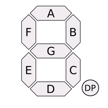 Here's the key to the segment lettering (click on the pic to jump to the Wikipedia page on 7-Segment displays from whence this image comes).
If I'd designed this VFD I'd probably have multiplexed the anodes for the three indicators in the left-most "digit" with the other anodes. I didn't design this, so they have separate anode leads in groups 10, 11, and 12. On the other hand they are enabled by the grid in position 13 (group 12). For some reason the calculator board drives these anodes during time slices 13 and 14, although the indicator grid is active only in time slice 13.
I'm still not sure what function pin 20 has. Perhaps it connects to some sort of ground shield to minimize radiated RF noise? But then I'd expect it to be connected to ground and it's not connected to anything on the PCB. I can't see any connections to it inside the VFD itself. I see some small wiggles in the 'scope trace but nothing significant. I suspect it's simply not connected to anything.
No comments:
Post a Comment