
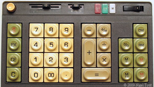
Looking at the arrangement of keys, the obvious arrangement is 8 columns of 5 rows. This is different than the 8x4 arrangement of the 141PF, but then the two keypads don't have quite the same layout or keys:
|
|

The Lattice iCEblink40-HX1K has several Digilent Pmod connectors. More properly, it's laid out for them but lacked the connectors. I ordered connectors and a PmodKYPD 4x4 matrix keypad from Digi-Key last week, and set about remembering how to write Verilog (it's been a year!).
The basics of decoding a matrix keypad are fairly simple:
- Provide resistive pull-ups on the rows, so un-driven rows read high (logic "1").
- Drive each column low (logic 0) one at a time in sequence.
- After a column goes low, look to see if any of the rows went low at the same time.
- The intersection of the column driven low and the row that senses low identifies the key that's been pressed.
- Mechanical keys don't switch cleanly from open to closed. Most of them bounce for some indeterminate period before settling in the closed state. Some even bounce while opening.
- Switches using conductive pads instead of metallic contacts may change state slowly, with the resistance decreasing as the contact area increases). Digital circuits really don't like being somewhere between 0 and 1; they draw more current and may oscillate.
- More than one key may be pressed at once. This can result in phantom keypresses of yet other keys.
I've been through this before, way back in 1981, when the small electronic design firm I worked for was designing a telephone for use in coal mines. The EE who designed the debounce circuit was an arrogant bastard who forbade me to change his design "because it works", despite the large box of "worn out" keypads we'd accumulated during development and testing. A peer of his suggested that I remove the offending circuit entirely and replace it with software debounce, justifying the change on the basis of hardware cost reduction. This I did, and we were then able to use ALL of the "worn out" keypads with a zero keying failure rate. Fortunately I was able to implement, test, and commit this change before he got wind of it, because when he heard about it he presented me with about 5 pages of assembly code containing the keypad debounce routine he insisted I had to use "because it works" (really because he wrote it). I politely declined, as my code was just a few dozen lines and was already in place.
For an interesting look at contact debouncing, check out Jack Ganssle's article on the subject here. The technique I developed in 1981 is very similar to the one he describes in the section titled "A Counting Algorithm" in part 2 of his article. The technique I use in Verilog is also very similar to what he describes in the section titled "An Alternative". If only the world-wide web had existed in 1981!
For this project I decided to start small and add functionality in stages. The first step, then, was to code the Verilog to scan the columns. This is actually pretty trivial:
1:    always @(posedge clk or negedge rst_n) begin
2:      if (~rst_n) begin
3:        col_drive <= 8'hff;
4:      end else if (clk_en) begin
5:        col_drive <= (col_drive[7:1] == 7'h7f) ? 8'hfe :
6:                     {col_drive[7:1], 1'b1};
7:      end
8:    end
I also coded the column decode modules, but I'll talk about that in another posting.
I'm much more familiar with Xilinx iSim than I am Aldec Active-HDL, so I tested my simple implementation by creating an ISE project. Simulation looked good and synthesizing it for the S6 LX9 helped identify bugs and get a feel for resource utilization. I synthesized it for the iCE40 and ran the Place and Route, providing a pin constraints file (.pcf) I hand-coded. After fighting with the programmer most of the evening I got it to load around midnight. And it didn't work. I saw what looked like a good 250us pulse going low every 2ms on one of the Pmod pins, but the other pins seemed to have noise on them. At this point I gave up and went to bed.
More in Part 2...
No comments:
Post a Comment