

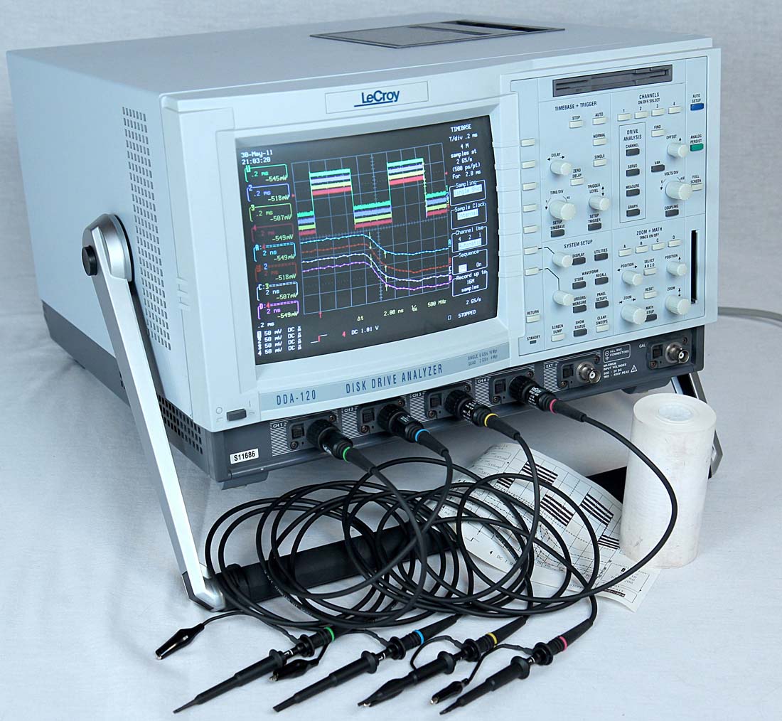
I was happy with it for a long time, but I always wished I had a digital storage 'scope like I'd used at some of my jobs. So after a dozen years of good service, the Tek has been moved aside in favor of my new oscilloscope, a LeCroy DDA-120 (basically an LC584AXL with some extra firmware installed). This one is mine:
As I mentioned earlier, one of the problems with the BSS83 transistor is that it's expensive. The 4004 has 1749 transistors in it, and even at 1K+ unit quantities that's over $560. Not all of them require the special characteristics that led me to the BSS83; in fact, more than 65% can be easily identified as not needing them. But what to substitute?
One option is the Diodes Inc. DMN26D0UT, which costs a hair over 6 cents each in 1K unit quantities. It would be an excellent choice, except that it's so tiny (1.6mm x 0.8mm) it's really hard to handle even with the microscope. Browsing through the datasheets online I came across the BSS138. The specs looked OK and it was cheap, so I bought some.
 Here is a recording of the turn-off characteristics of the three. The sources of the transistors are connected to ground, and the drains are each pulled to +5V by 10K ohm resistors. The horizontal scale is 200ns per division, and the vertical is 1V/div.
The yellow trace is the gate voltage on all three transistors going from +4.5V to 0V. The green trace shows the turn-off characteristics of the BSS83. It's there as a "gold standard". The blue trace is the DMN26, and the magenta is the BSS138. Wow, is it ever slow! While the drain of the BSS83 rose to 1V in about 40ns, and the DMN26 in about 100ns, the internal capacitances of the BSS138 are so high it took 250ns to do the same.


Putting it into the DRAM circuit showed just how bad it was. The picture on the left is shows the circuit using one of the fast transistors to drive the read and write enable logic during a refresh cycle. The blue trace is the read enable line, the green trace is the write enable line, and the magenta trace is the signal selecting the row. Note that while neither enable line reaches +5V, they're both solidly at +4V, which is good enough.
Next is the same circuit using the BSS138 to drive the row select. The rise time is so slow that it causes a serious degradation in the enable line signals. It's barely reaching +5V before the end of the cycle, about 800ns after it needs to be there. That's not good enough.
Could I have identified this problem with my old scope? Maybe. But it would never have been so obvious, and with only two traces visible at a time the relationship would have been hard to see.
No comments:
Post a Comment